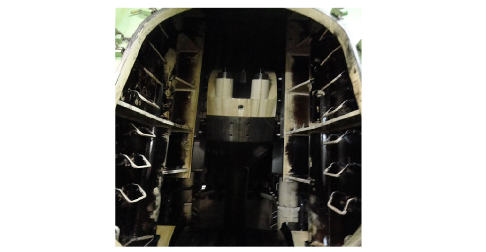
Crosshead is attached on the upper part of the connecting rod, which connects the con-rod to the piston rod. The guide and the guide shoe runs on the guide rail to support the crosshead pin and to transfer the side thrust of the crosshead to the engine frame.
In some old MAN B&W engines and SULZER RND engines, the piston rod passes through a bore in the crosshead and is bolted from the bottom by means of fine threaded nut.
In the new design engines such as MAN SMC/ ME and SULZER RTA/ RT flex, the pison rod palm rests on the crosshead flat surface and four hydraulic bolts are used to tie them together.
Guide and guide shoe, along with the connecting rod and crosshead, is an important arrangement as the guide directs the guide shoe in reciprocating direction while absorbing the side thrust produced during the motion of the connecting rod.
The guide comprises of guide rail (normally integrated/ bolted with the frame) and guide plates, in which, the guide shoe moves up and down.
MaterialCrosshead: The crosshead bracket is made up of steel casting in which the pin is shrink-fitted to form complete crosshead unit.
Crosshead pin- The crosshead pin is made of high strength nitride steel with excellent surface finish which helps in lubrication of crosshead bearing.
Guide Plate: Guide plates are made up of cast iron. Sometimes shims are provided for adjustment of guide plates.
Guide Shoes: Guide shoes which are accommodated in the A frame, and fitted both forward and aft of crosshead, are normally made of white metal lining with slipper surface. Lubricating oil grooves are cut into the guides for lubrication.
The crosshead pin is fitted with a loose fitting pin which allows a small degree of movement (about 1mm) between the guide shoe and the pin, giving better alignment.
Also, two long studs pass through the crosshead pins horizontally and secure the pins to the brackets at the back.
The telescopic pipes for lubricating and cooling oil are supported by the crosshead brackets at the front of the piston rods and the guide shoes are bolted to these brackets at the back.
Each side crosshead is made up of steel casting, into which the crosshead pin is shrunk fitted, with the side rod screwed into the top of the casting.
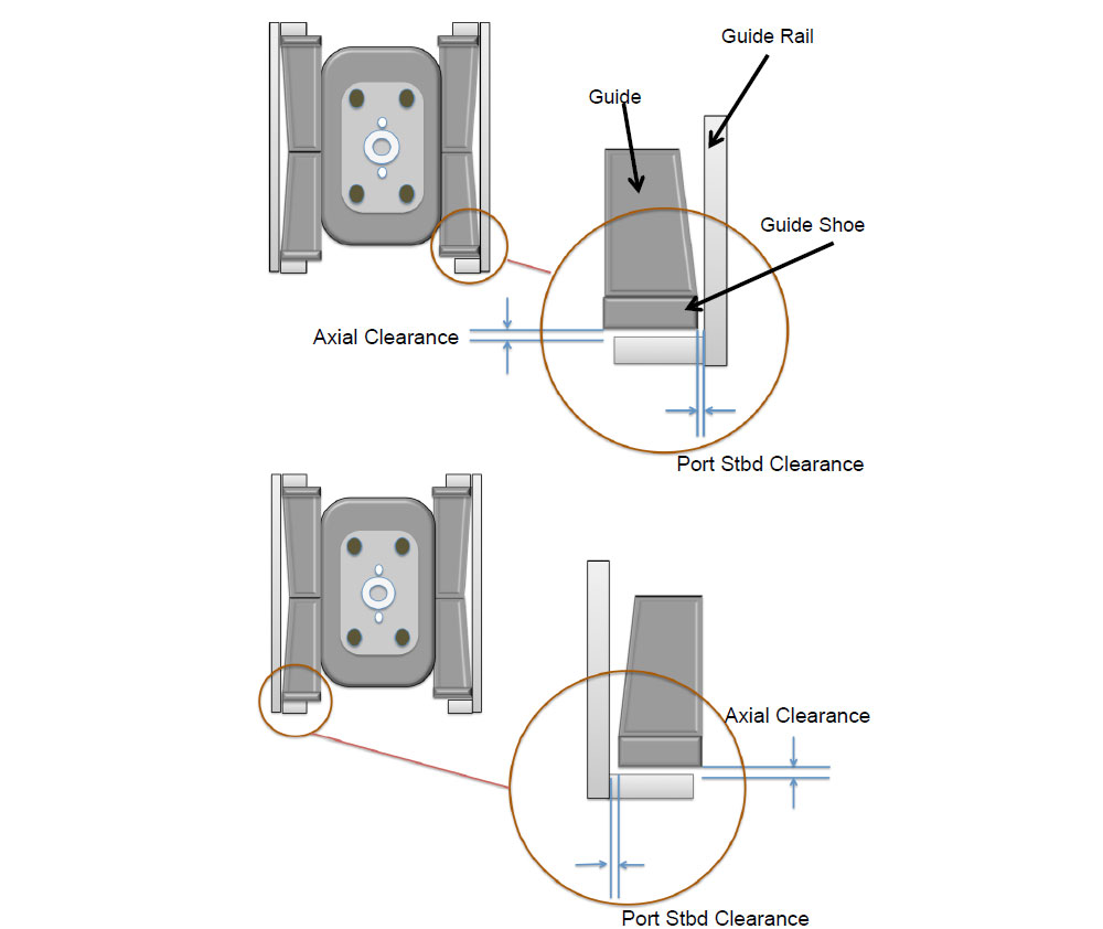
Inspection Check the lubrication oil flow in the crosshead Check the telescopic or articulated pipe connections and securing arrangement Check for any leakage from telescopic pipe Check all the locking plates and locking screw in the crosshead securing nuts Check the near edge area of piston palm over crosshead for any distortion Check clearance of crosshead bearing Check guide and rail clearances Check for any squeezed out white metal between bearing and pin Check the lube oil hole between crosshead and piston rod for chocking or deposits Check for scratching marks on the crosshead pin Check the surface finish of crosshead pin Check the surface of guide rail for any breakage of rail path Check condition of guides for any white metal flakes Check the oil wedges provided in the guide shoes for deposits and any breakage ClearnacesThe most important measurement of conrod, guide shoe assembly is the clearance between the guide and guide shoe. This clearance is checked by using feeler gauge at three different places:
Between guide shoe and guide plate at port – starboard direction Between guide shoe and guide rail in axial direction Between Guide shoe and crosshead pinEnsure to check the manual for required clearances and accordingly use feeler gauge of proper thickness, as clearances are very small in this area.
