1.1 General requirements
1.1.1 Definitions
The following terms and definitions are used:
|
cargo mass P |
gross mass of cargo unit, during lifting placed virtually in the level of p metres above base |
|
top-mass of crane(s) Q |
part mass of crane jib, during lifting placed virtually in the level of q metres above the sea-going level of the jib-top |
|
mass of suspension gear R |
mass of suspension gear, during lifting placed virtually in the level of r metres above weather deck level |
|
GMC during lifting |
metacentric height with (P+R+Q) in lifting level |
|
maximum heeling moment |
moment of (P+R+Q) at the maximum outreach from neutral position of crane jib |
|
counter-ballasting moment |
moment of transverse ballast transfer |
|
centre of gravity of cargo unit |
c.o.g., position supplied by shippers in three dimensions |
|
centre of suspension |
point of connection of suspension arrangement to lifting tackle |
|
suspension arrangement |
arrangement of traverses, spreaders, slings and shackles |
|
hanging forces |
vertical forces in suspension arrangement |
|
effective forces in suspension |
effective forces in elements of a suspension arrangement |
|
suspension angle |
angle between hanging force and effective force |
|
stable suspension |
arrangement with (virtual) c.o.g below centre of suspension |
|
unstable suspension |
arrangement with (virtual) c.o.g above centre of suspension |
|
WLL |
working limit load as marked on lifting element |
|
BL |
breaking load as declared in certificate |
|
SF |
safety factor (BL/WLL) |
|
slinging height |
height from bottom of cargo unit to lifting tackle |
|
hoisting distance |
distance from hatch top to lifting tackle |
|
lifting fittings |
fittings on cargo unit declared suitable for lifting |
|
slinging area |
area on cargo unit declared suitable for placing slings |
1.1.2 Information from the shipper
For safe lifting and placing a heavy cargo unit on board the following information is required from shippers:
- The mass of the unit in metric tonnes and its main dimensions including all attachments and protrusions.
- A scale drawing of the unit showing top view, side view and front view as appropriate. This drawing should include the position of the centre of gravity relative to the base line and the front line in side view and relative to the centre line in top view.
- The scale drawing should further contain the position and nature of lifting fittings (e.g. chain plates, D-rings, trunnions), if supplied, or the position and size of slinging areas.
- A declaration of the WLL and the BL of the lifting fittings and a note on the suitability of the lifting fittings for securing the cargo unit with particular consideration of possible limitations to the direction securing forces.
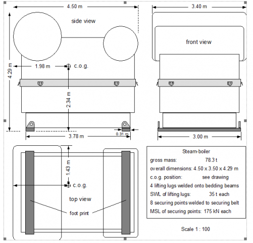
Figure 1.1.1: Sample scale drawing
1.1.3 Planning essentials and documentation
The planning of a lift-on or lift-off procedure shall include the following aspects:
- Selection of stowage place with regard to the crane's SWL-ranges. This task is usually integrated into the general stowage planning and should be documented accordingly.
- Checking the expected metacentric height GMC of the vessel during lifting. This task shall be accomplished by an appropriate stability calculation and documented in the cargo operations log. Details are given in Chapter 1.2.1 below.
- Arranging the required counter-ballasting moment with due regard to the expected maximum heeling moment. This task shall also be accomplished by an appropriate calculation and documented in the cargo operations log. Details are given in Chapter 1.2.2 below.
- Designing an appropriate suspension arrangement with due regard to:
- outfit of the cargo unit in question with lifting fittings or slinging areas,
- available lifting material of sufficient strength and dimensions,
- available hoisting distance to be greater than the slinging height,
- positive stability of the suspension arrangement,
- distribution of forces in suspension elements and control of suspension angles.
Depending on the complexity of the individual case, a scale drawing of the suspension arrangement should be prepared that allows the determination of all data necessary to check the critical features of the arrangement. Details are given in Chapters 1.3 to 1.5 below.
The results should be documented in the cargo operations log stating as a minimum the
- compliance with strength limits (actual loads less than WLL-figures),
- positive stability of the suspension arrangement,
- sufficient hoisting distance at all times.
1.2 Ship's stability
Loading or unloading of heavy cargo units with ship's own gear has two serious effects on the ship's stability:
- Reduction of GM due to the lifted mass being placed virtually at the crane boom top.
- Generation of large heeling moments, which may cause the vessel to list.
With the modern heavy lift cranes used in the Beluga fleet the maximum permissible list is restricted to 2°. Therefore it is advisable, to keep the list close to zero at all times, in order to save an adequate margin for the operation of the ballast pumps, which are used to compensate the heeling moments.
It is the duty of the ship's Chief Officer to check by calculation that during the lifting process
- the GMC of the vessel (corrected for free liquid surfaces in tanks) is at least 1.00 m, and
- the amount of transferable ballast is sufficient for counter-acting the heeling moment.
This is explained in more detail in the following sub-chapters.
1.2.1 Minimum initial stability
Beluga ships are operated under IMO stability criteria. The IMO Code on Intact Stability does not contain a specific rule addressing the residual stability during heavy lift operations. This does, however, not dispense the ship's staff from evaluating this problem in a careful manner.
In the course of pre-planning a heavy lift operation, a stability calculation must be carried out by means of the ship's approved stability computer, which reflects the actual condition of the ship at the time of the intended operation with regard to cargo, bunkers and ballast on board and free surfaces in slack tanks.
The result of this calculation must be expanded to express the conditions of the lifting situation by placing the specific mass of the unit to be loaded or unloaded, together with the mass
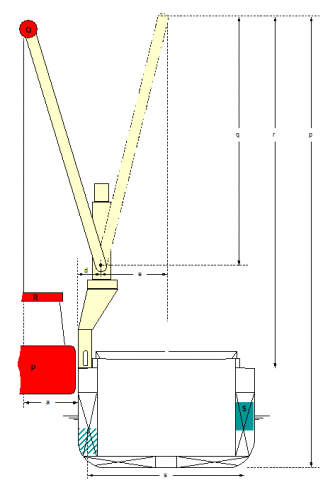
Figure 1.2.1: Essential data for controlling ship's stability in lifting operations
of the suspension gear into top-level of the crane boom. This level should be estimated as the highest position of the boom top during the operation.
In detail: The mass P of the cargo unit must be placed into the lifting level of p metres above base. The top mass of the crane(s) Q must be shifted by q metres from the sea-going level to the lifting level. The mass of the suspension gear R (slings, shackles, hooks, traverses) must be shifted by r metres from the deck level to the lifting level (see Figure 1.2.1).
The result of this calculation is the metacentric height GMc for the lifting condition.
The GMc during lifting shall not be less than 1.00 m.
In case of a smaller figure additional ballast must be taken in and/or advice from the head office should be obtained.
1.2.2 Preparation of heeling tanks
In order to keep the ship upright during all phases of the lifting operation the ship's heeling pumps must be used. To this purpose a sufficient transfer capacity of ballast water in terms of heeling moment must be prepared before the lifting operation can be started. The required amount of ballast for compensating the heel is calculated as follows:
The ship is assumed upright before commencement of lifting with the crane tops in fore and aft position at the resting distance d from the port rail. The expected outreach from the ship's side is the distance a. Thus the total heeling lever for lifting from outboard is (d + a). The heeling lever to the opposite side for landing the cargo unit inboard is e, which depends on the intended stowage position (see Figure 1.2.1).
The maximum heeling moment is (d + a) × (P + Q + R) or e × (P + Q + R), whichever is greater. A sufficient capacity of ballast water S with a transverse lever s is required to obtain an equal counter-ballasting moment. This lever should be taken as an average value for suitable side tanks of the particular ship. The necessary amount of water is:

This amount of water, plus a margin of 10 %, should be available for pumping into either direction.
1.3 Lifting Material
Project carriers in the Beluga fleet are equipped with a standard set of wire rope slings and grommets, shackles and traverses for lifting heavy cargo units.
1.3.1 Wire slings and grommets
The details of wire rope slings and grommets are addressed to in the particular inventory list on board.
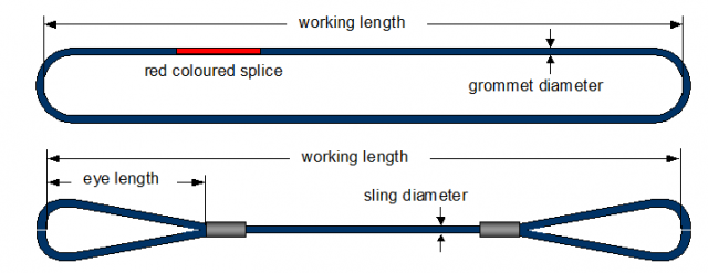
Figure 1.3.1: Wire rope lifting grommet and sling
1.3.2 Shackles
The details of shackles are addressed to in the particular inventory list on board.
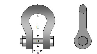
Figure 1.3.2: Lifting shackle
1.3.3 Traverses
The equipment of product carriers in the Beluga fleet with traverses depends largely on the current engagement with the transport of heavy lifts. The following overview shows the available items and their properties.
Traverses of SWL = 250 t are available in different lengths.
|
length |
3.0 m |
4.0 m |
5.0 m |
6.0 m |
7.0 m |
8.0 m |
9.0 m |
|
own mass |
1.10 t |
1.27 t |
1.42 t |
1.58 t |
1.73 t |
189 t |
2.00 t |
Figure 1.3.3: Traverse of SWL = 250 t
For handling heavy units of relatively small size with two cranes a traverse is used, which accommodates the usual lifting double hooks on both ends and provides trunnions on both sides for attaching slings or grommets (Figure 1.3.4).

Figure 1.3.4: Traverse of SWL = 460 t
1.3.4 Inspection and maintenance
All lifting equipment must be carefully inspected before and after each use. Wire slings and wire grommets shall be preserved with wire rope grease and threads of shackle bolts shall be greased at suitable intervals to avoid corrosion.
Wire ropes must be discarded if at a length of 8 times the wire diameter more than 10 % of the single wires are visibly broken. Shackles must be discarded if the diameter of jokes or bolts is locally reduced by 10 % from abrasion or if visibly deformed. Rejected lifting material must be disposed for transport to a scrap yard. The receipt of such disposal must be kept on board and the company informed accordingly. Disposal of such material over board at sea is not permitted by Beluga Shipping.
Any employment of lifting equipment for loading or unloading heavy cargo must be entered into the specific journal, as well as any activity regarding maintenance or discarding of equipment.
1.4 Lifting Arrangements
1.4.1 Determinacy of suspension arrangements
Arrangements with two lifting points are quite often used for longish units (Figure 1.4.1).
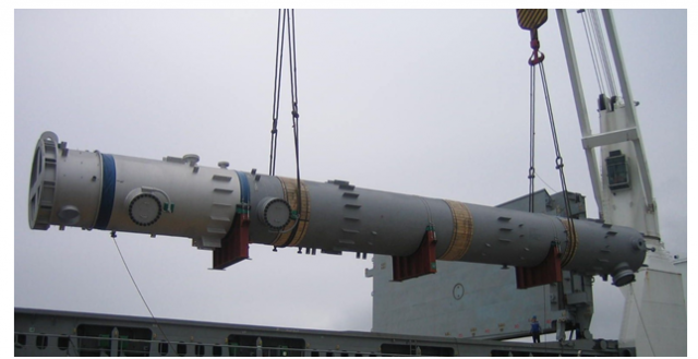
Figure 1.4.1: Suspension arrangement with two lifting points
The distribution of the load between the two lifting points depends on their position in relation to the c.o.g., following the general rule that the hanging forces are inversely proportional to their distances to the c.o.g. (Figure 1.4.2). The forces are calculated as follows:


Figure 1.4.2: Hanging forces in an asymmetric two point suspension
Arrangements with three lifting points are scarcely used. The precise determination of the hanging forces may require a lengthy calculation.
Suspension arrangements with more than three lifting points are statically indeterminate. The hanging forces cannot be precisely determined but only estimated with reasonable accuracy (see chapter 1.5). It is of utmost importance that the length of slings complies with the geometry of the suspension arrangement.
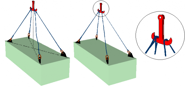
Figure 1.4.3 shows a suspension arrangement with four slings shackled onto four adequate eye plates on the unit. Two of the slings appear to be a bit too long resulting in overloading the two other slings.
This deficiency may be avoided by an arrangement shown in Figure 1.4.4, where two of the slings have been replaced by one sling of double the length, run as a "loop over the hook". In this way the statically indeterminate four-point suspension has been converted into a statically determinable three-point suspension.
Such "loop over the hook" slings should not be used on both ends of the cargo unit in order to avoid the risk of tilting.
|
Figure 1.4.3: Four slings with obvious imbalance of load distribution |
Figure 1.4.4: Even load distribution with one "loop over the hook" sling |
Lifting with two "loop under the bottom" slings will usually provide an equal distribution of the load to all four parts (see Figure 1.4.5). The risk of tilting is minimal due to the friction of the slings around the bottom of the cargo unit.
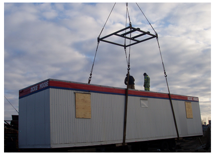
Figure 1.4.5: Lifting with two loops under the bottom
1.4.2 Single gear arrangements
Single gear arrangements use only one crane for lifting. The c.o.g. of the unit will be vertically under the lifting tackle.

Figure 1.4.6: Single gear arrangement with transverse traverses
The slings in Figure 1.4.6 are connected to solid trunnions fitted to the base frame of the unit. Also this suspension arrangement is statically indeterminate and therefore needs four slings having the same length.
If the slings run as loops under the bottom of the unit it is important to avoid slipping of the slings to the centre of the unit. The favourite option is to use a longitudinal traverse that keeps the slings vertical (Figure 1.4.7).
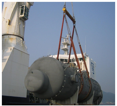
Figure 1.4.7: Single gear arrangement with longitudinal traverse
Another option, frequently used with light cargo units, are running straps or slings. But it is dangerous to use running slings for heavy lift units. The wire will be cut in the eye during tightening. Therefore running slings are not permitted for heavy lifts in Beluga Shipping.
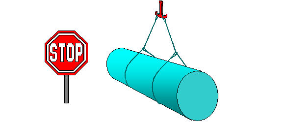
Figure 1.4.8: Never use running slings for heavy lift units
1.4.3 Double gear arrangements
Double gear arrangements are used when two cranes are needed for lifting the cargo unit safely. The principles of determinacy of hanging forces are the same as with single gear arrangements. A traverse for connecting both lifting tackles is generally not necessary if the cargo unit is long (Figure 1.4.9).
If the cargo unit is small a traverse should be used (Figure 1.4.10). This avoids any contact between the crane tops and may be moreover necessary to reduce the outreach of the crane booms to utilise their full lifting capacity.

Figure 1.4.9: Double gear arrangement without longitudinal traverse
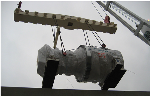
Figure 1.4.10: Double gear arrangement with longitudinal traverse
In case of an asymmetric double gear suspension arrangement the hanging forces in slings and in lifting tackles must be calculated using the principle of "inverse proportionality". The load in the slings depends on their distances to the centre of gravity of the unit e1 and e2 (see Figure 1.4.11).

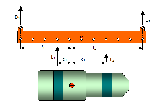
Figure 1.4.11: Asymmetric double gear suspension arrangement
1.4.4 Tilting due to offset of centre of gravity
The layout of a lifting arrangement should be generally designed under the assumption of a centre of gravity of the particular cargo unit that is in or very close to its geometrical centre unless informed otherwise by the shipper. Any unexpected eccentric position of the centre of gravity or transverse deviation from the advised position will tilt the suspended cargo unit and distribute the loads in the suspension gear unevenly.
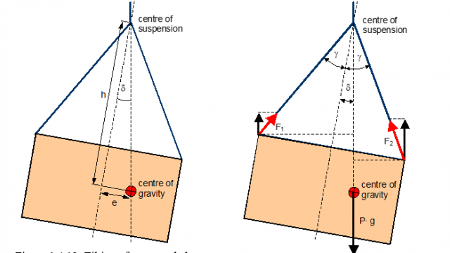
|
Figure 1.4.12: Tilting of a suspended cargo unit due to eccentricity of c.o.g. |
Figure 1.4.13: Uneven distribution of forces in slings |
The magnitude of a tilt angle d depends on the eccentricity e of the c.o.g. and on the vertical distance h of the c.o.g. from the suspension centre (Figure 1.4.12). The hanging forces are greater on the low side of the tilted unit (Figure 1.4.13).
Another disadvantage of tilting may be the difficulty of placing the unit at the intended stowage position. This problem can be solved by elongating the sling(s) on the high side, e.g. with by inserted shackles. However, this does not equalise the different loads in the slings, as demonstrated by Figure 1.4.14.
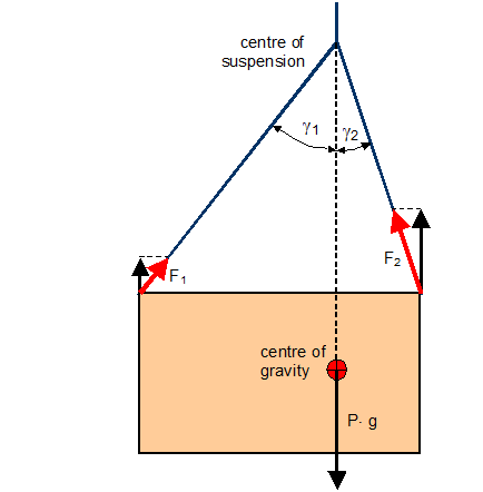
Figure 1.4.14: Suspension rectified by adapting the length of slings.
A suspension arrangement is more liable to tilting, even with a small eccentricity of the c.o.g., if the slings are fastened to traverses above as shown in Figure 1.4.15.
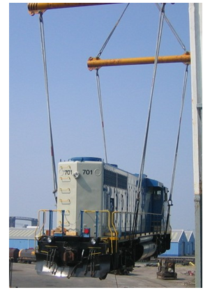
Figure 1.4.15: Suspension arrangement with traverses, slings fastened below c.o.g.
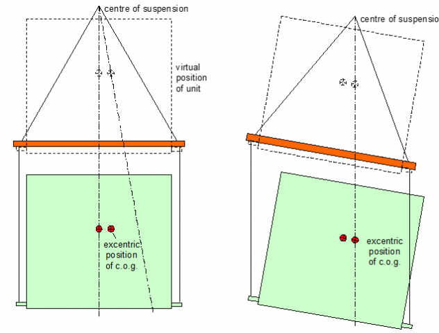
An effective "virtual" position of the c.o.g. reduces the distance to the centre of suspension (Figure 1.4.16). The cargo unit may touch the vertical slings causing damage to a sensitive surface and produce mechanical strain to the sling (Figure 1.4.17).
|
Figure 1.4.16: Virtual position of a cargo unit suspended under a traverse |
Figure 1.4.17: Actual suspension with eccentric c.o.g |
1.4.5 Stability of suspension arrangements
If the centre of gravity of the cargo unit c.o.g. is positioned below the centre of suspension c.o.s. the arrangement is stable, unless a tilting angle due to temporary external influences like wind or swell is less than the suspension angle of slings. Figure 1.4.18 shows three stable arrangements.
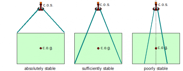
Figure 1.4.18: Stable suspension arrangements
If the c.o.g. is positioned above the c.o.s. the arrangement is unstable and will capsize at the least disturbing influence (Figure 1.4.19).
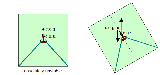
Figure 1.4.19: Unstable suspension
In suspension arrangements with traverses the virtual position of the c.o.g. is always above the actual position by the length of the vertical slings (see also Figures 1.4.16 and 1.4.17). Such arrangements become unstable if the virtual c.o.g. is located above the c.o.s. of the arrangement.

Figure 1.4.20: Stable and unstable arrangements with traverse
1.5 Lifting Calculations
In the course of planning the suspension gear for lifting of heavy cargo units, the required WLL-figures of slings, shackles and traverses must be determined by calculation with due regard to safety factors adopted by Beluga Shipping.
In cases with asymmetric suspension it may additionally become necessary to precisely determine the required length of slings.
1.5.1 Safety factors
The Working Limit Load (WLL) of a suspension element is a figure that indicates the permissible load (mass) given in metric tons to be lifted vertically by this particular element. The specification of WLL generally incorporates a safety factor (SF) against the nominal breaking load (BL) of that element.
The nominal breaking strength of lifting material is increasingly supplied with kN-marking by manufacturers and chandlers. BL-figures in tonnes may be obtained by dividing the kN-figures by the g-factor of 9.81 m/s2.
The relation between BL and WLL reads:

Safety factors for suspension elements in heavy lift operations on ships are not governed by public legislation. Beluga Shipping uses the following safety factors for suspension material:
|
Material |
Safety factor |
|
Shackles |
6 |
|
Wire grommets |
5 |
|
Wire slings |
4 |
|
Polyester grommets |
7 |
|
Steel belts |
6.7 |
The WLL of traverses is directly declared and documented by the manufacturer.
1.5.2 Determination of required WLL-figures
The required WLL-values in a suspension arrangement shall be determined in three steps:
- Evaluation of hanging forces
- Calculation of effective forces in shackles and slings
- Selection of required WLL
In case of a symmetrical suspension arrangement the hanging forces may simply be obtained by dividing the weight of the unit by the number of slings. In asymmetrical arrangements the hanging forces must be calculated as shown in chapter 1.4.1, using the principle of inverse proportionality.
The effective forces in shackles and slings depend on the suspension angle following the equation:
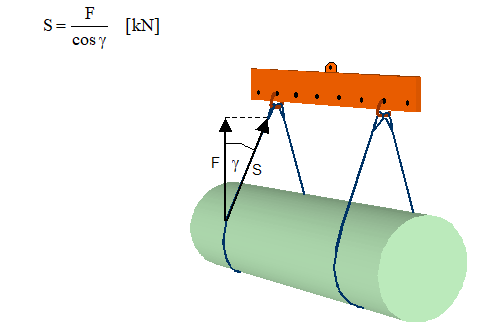
Figure 1.5.1: Suspension angle g
1.5.3 Determination of sling lengths
A precise determination of sling length is necessary if a unit shall be lifted with an asymmetrical suspension arrangement. This task requires a fairly exact drawing of the unit with top view and side views containing all necessary details of lifting appliances, like trunnions or eye plates, and the position of the centre of gravity of the unit.
The length of slings in a suspension arrangement should be determined in three steps:
- Decision on "slinging height"
- Determination of the geometrical gross length of slings
- Calculation of the effective net length of sling by considering shackles, bends etc.
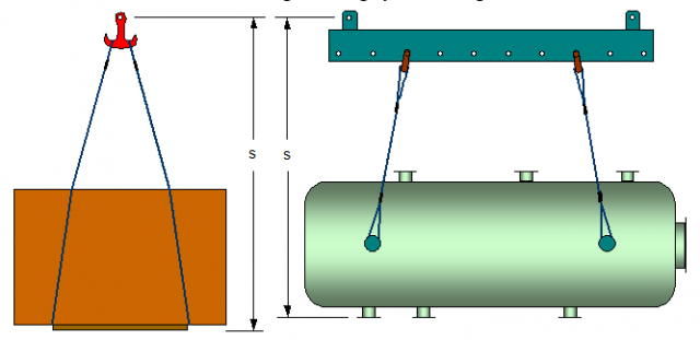
Figure 1.5.2: Slinging height s
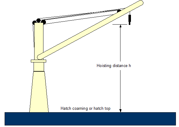
Figure 1.5.3: Hoisting distance h
The slinging height (Figure 1.5.2) is the total distance from the bottom of the unit up to the bolt of the crane hook. This distance must not be greater than the available hoisting distance (Figure 1.5.3), which is usually no problem with modern crane equipment.
The geometrical gross length of a sling is the spatial distance from the distinguished lifting appliance of the unit to the upper side of the hook or shackle or traverse trunnion.
The effective net length of each sling is obtained by deducting the length of shackles with due consideration of the radii of shackle bolt and shackle body.
1.5.4 Forces in spreader support wires
Occasionally cargo units are lifted with spreaders instead of traverses. These spreaders have the beneficial effect that the load in the slings is not increased by the slinging angle g. However, the spreaders themselves must be supported by extra slings which have to take the additional load created by the suspension angle g. Figure 1.5.4 shows the different loads in the arrangements with traverse and spreader.

Figure 1.5.4: Lifting arrangement with traverse (left) and spreader (right)
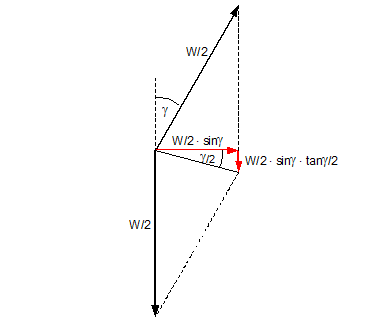
Figure 1.5.5: Transverse and vertical forces (red) to the spreader boom
The load LS in the spreader support wires results mainly from the vertical component of the resultant of the forces in the sling, but must also take account of the weight S of the spreader itself. For each support wire, with W and S given in t, the load LS is:

The support wires have to carry a lot more than only the weight of the spreader and must be dimensioned accordingly.